Full internal Di2 retromod on 06 TCR Advanced LE (6.3kg)

Who are you (no off-topic talk please)

Moderators: MrCurrieinahurry, maxim809, Moderator Team

User avatar
Kimmoth
Posts: 87
Joined: Wed May 30, 2018 11:33 am
Location: Melbourne, Oz
Contact:

by Kimmoth

So I've done a custom Di2 loom, using three of the hugely expensive wires to give me a plug each for shifters, derailers and battery, and also spliced onto the BCR2 since I've deleted the the charging port (that plug and jack is actually repurposed to sit between the frame and fork, in the top of the downtube).

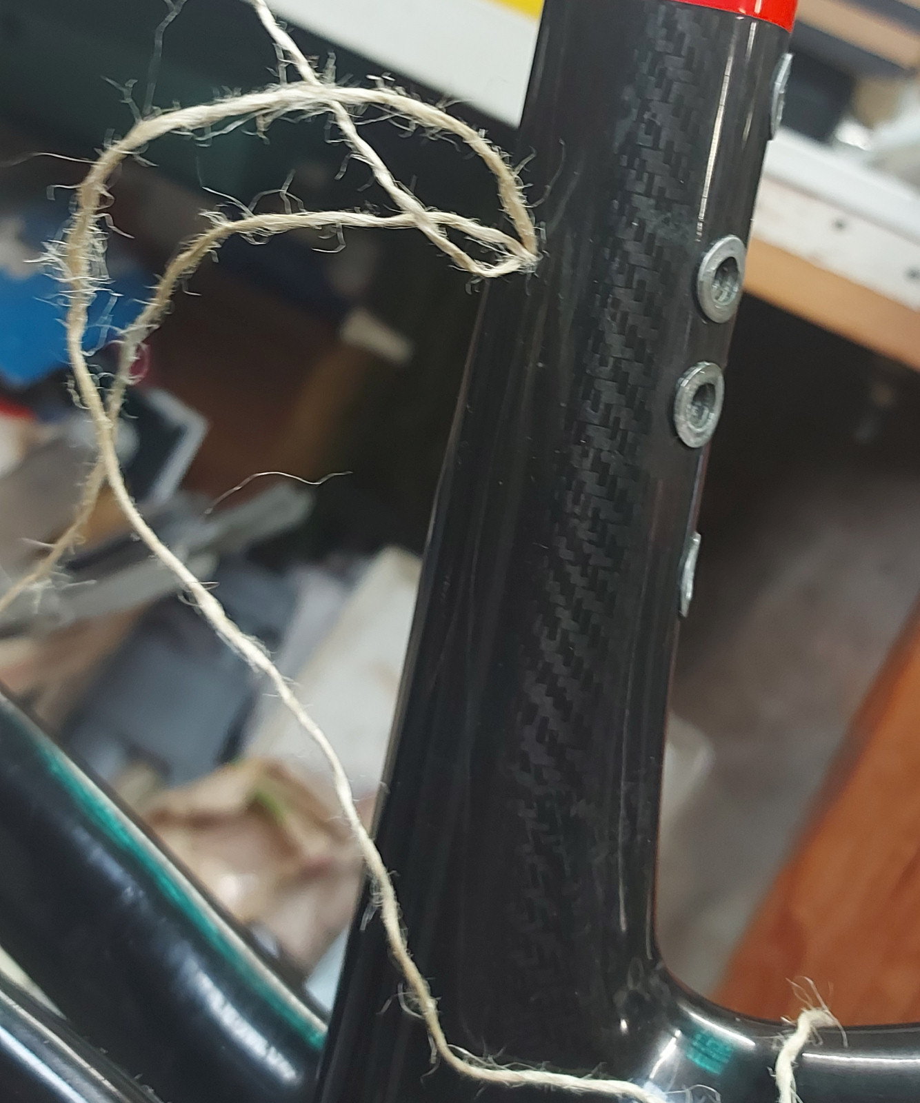
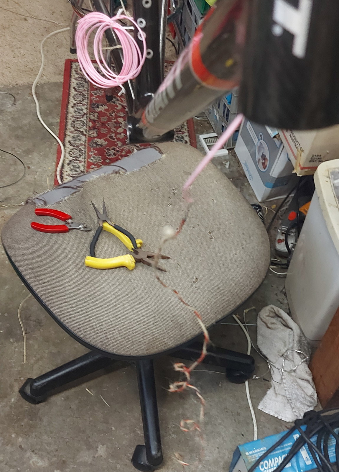
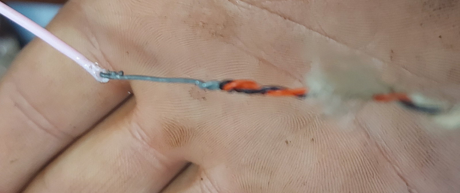
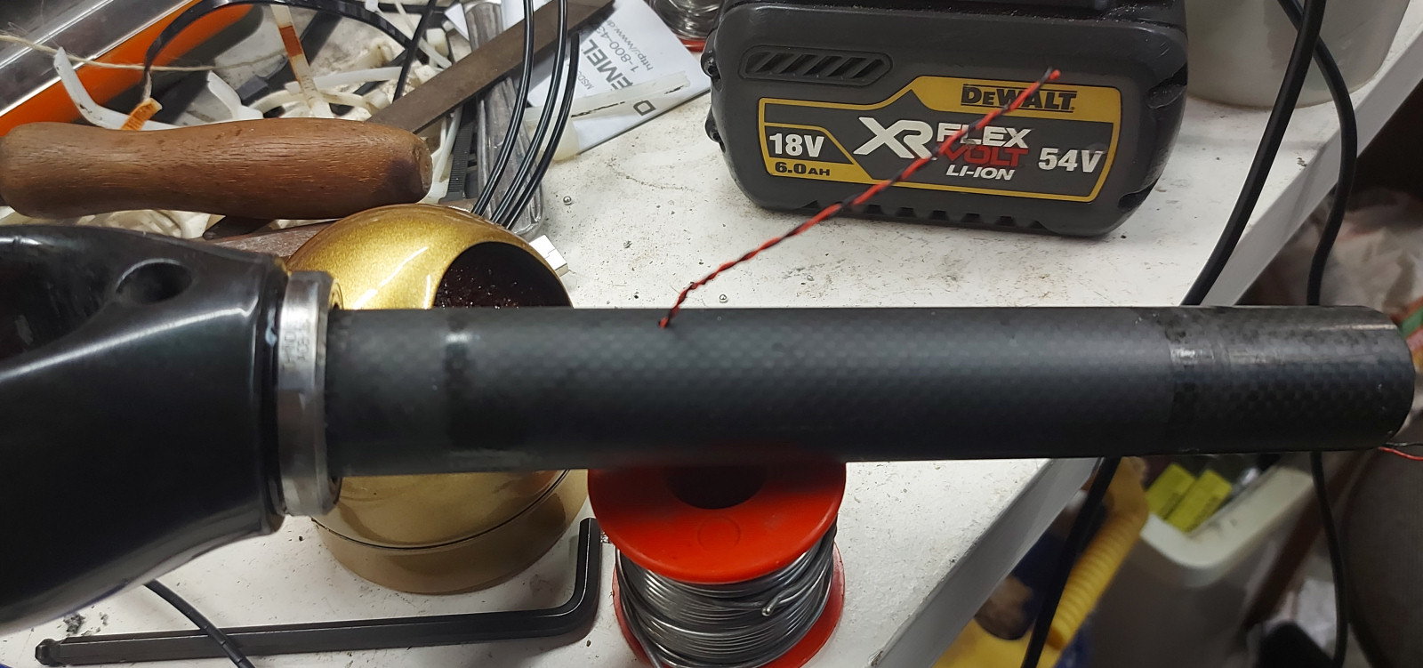
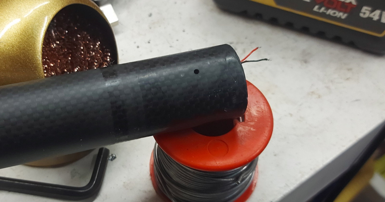
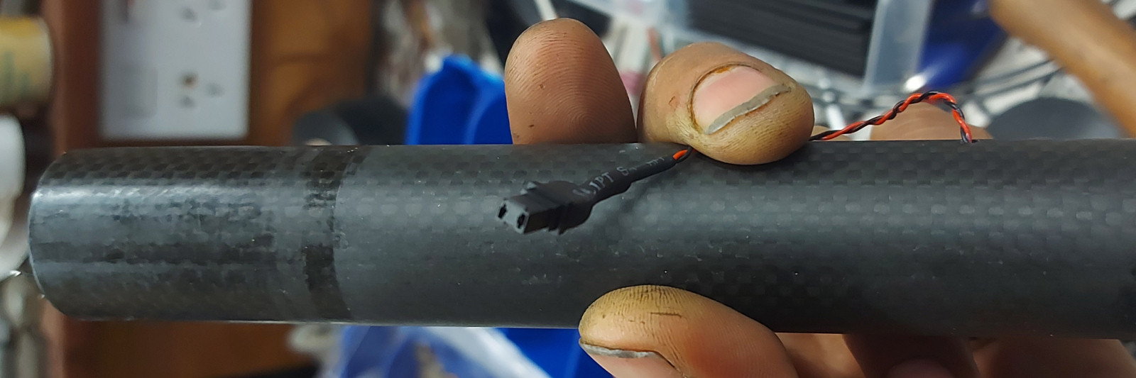
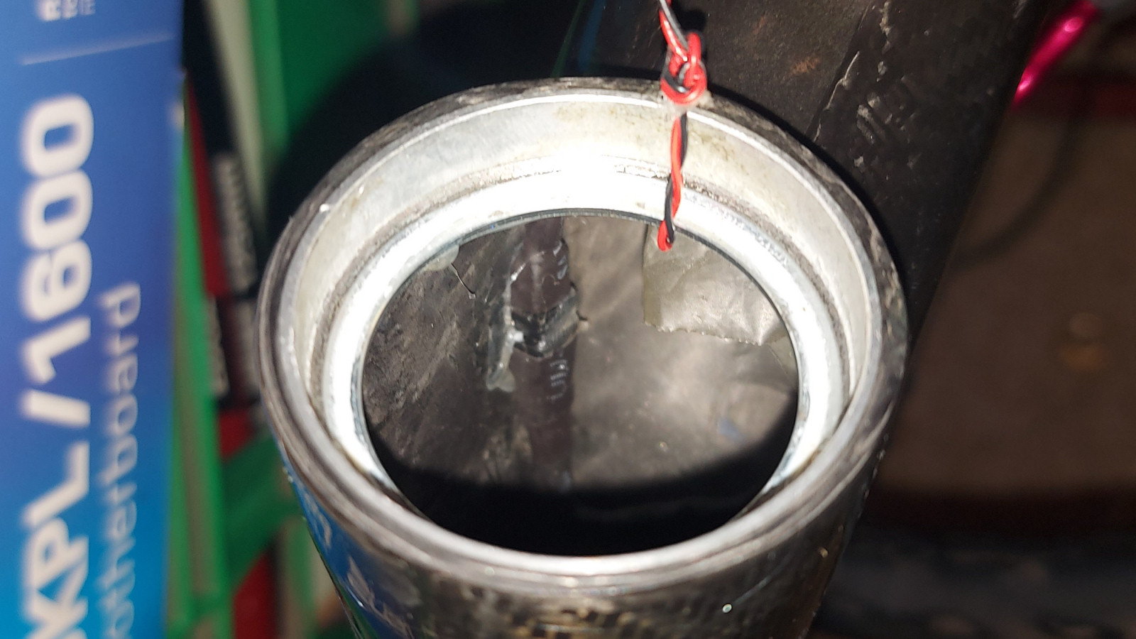
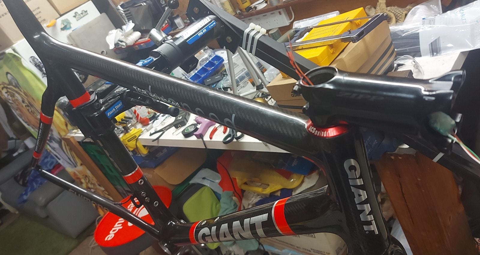
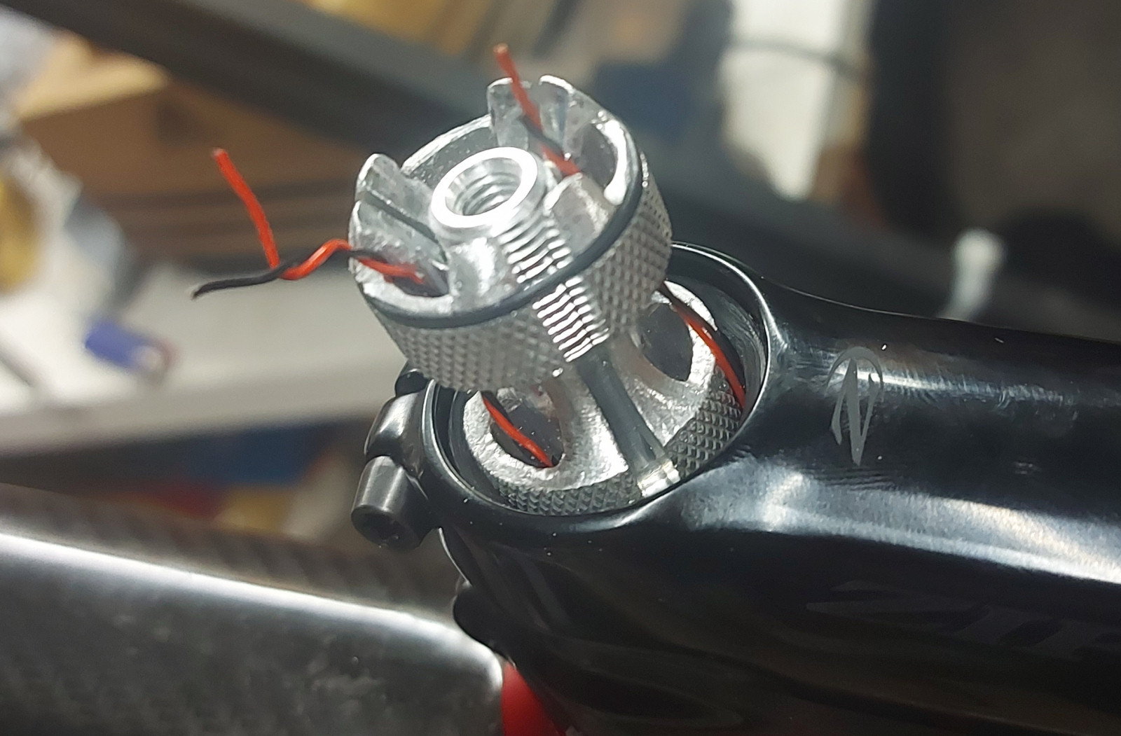
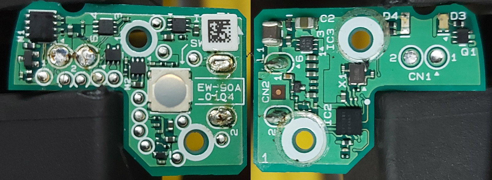
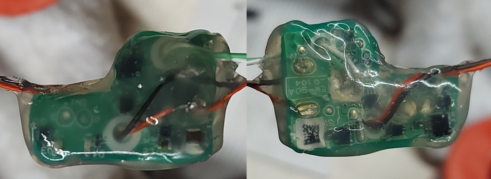
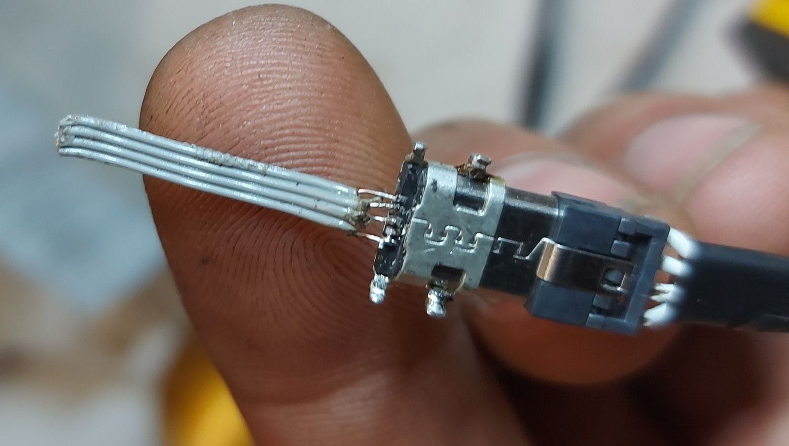
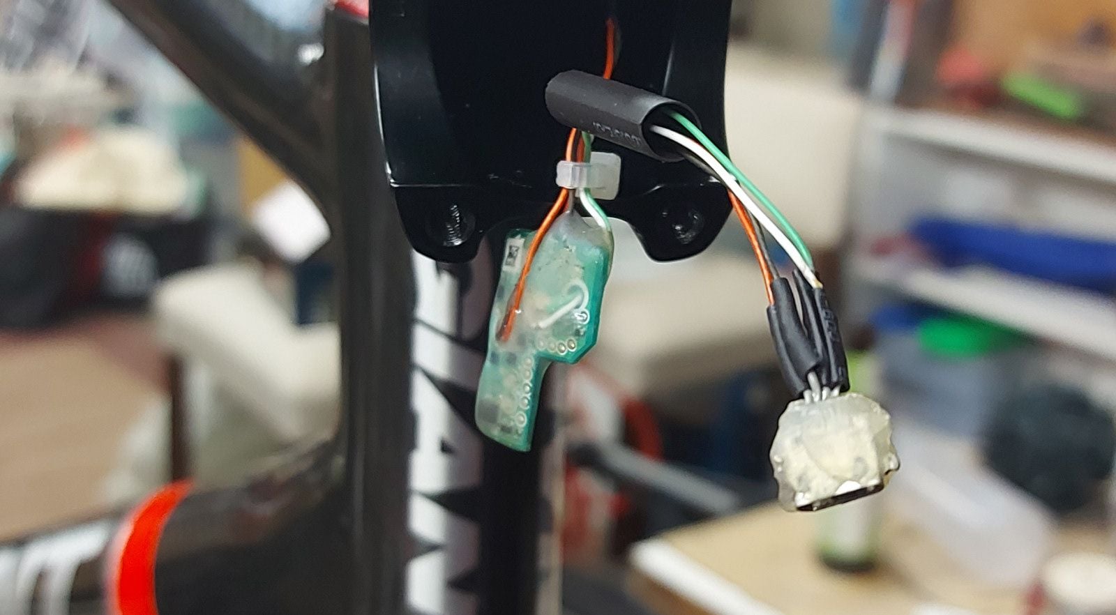
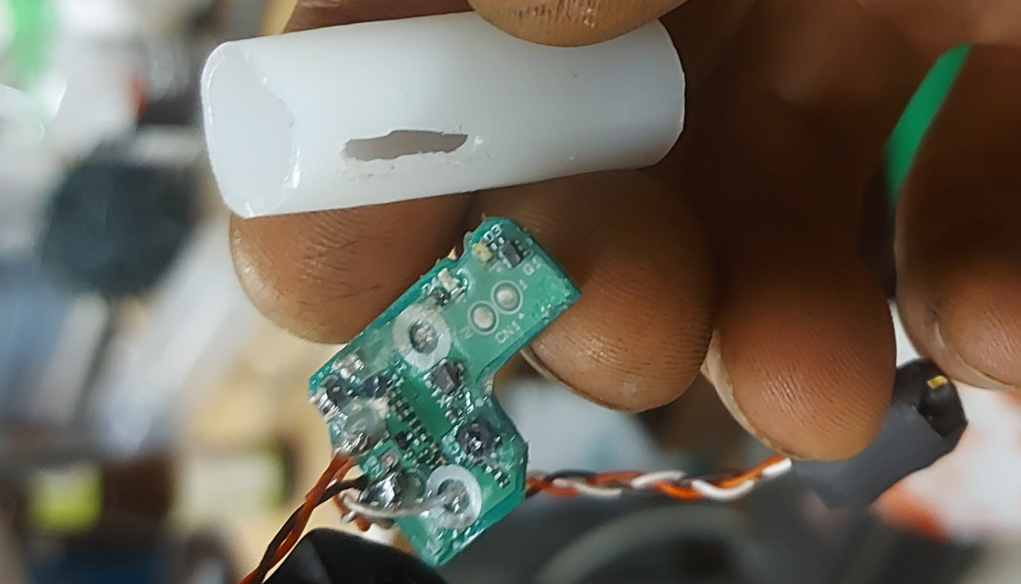
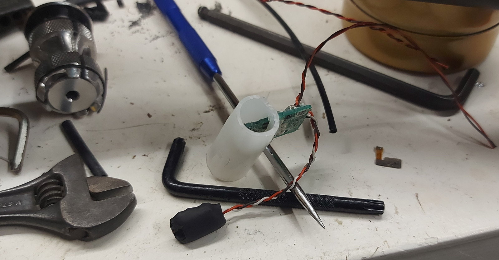
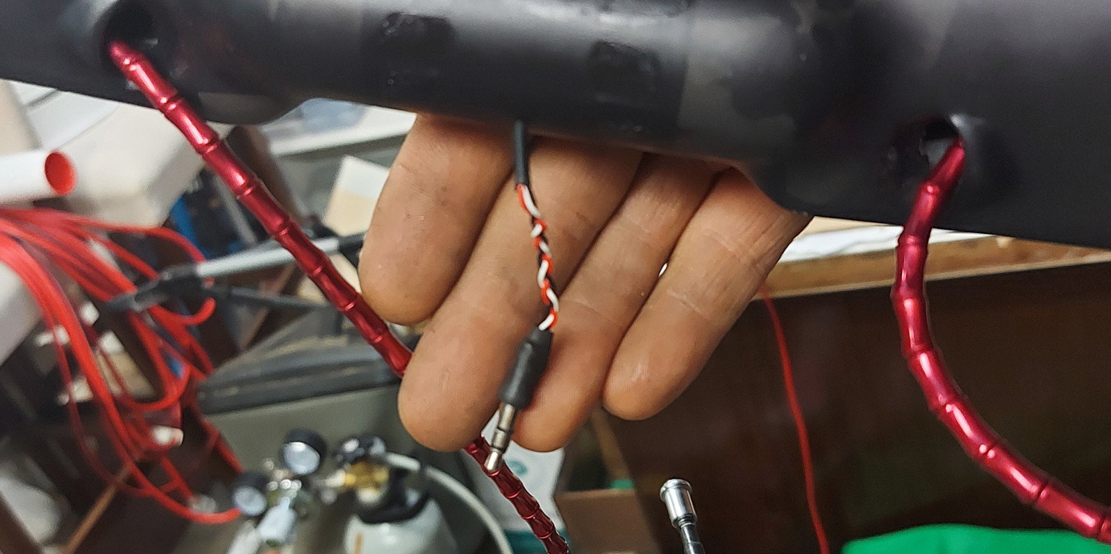
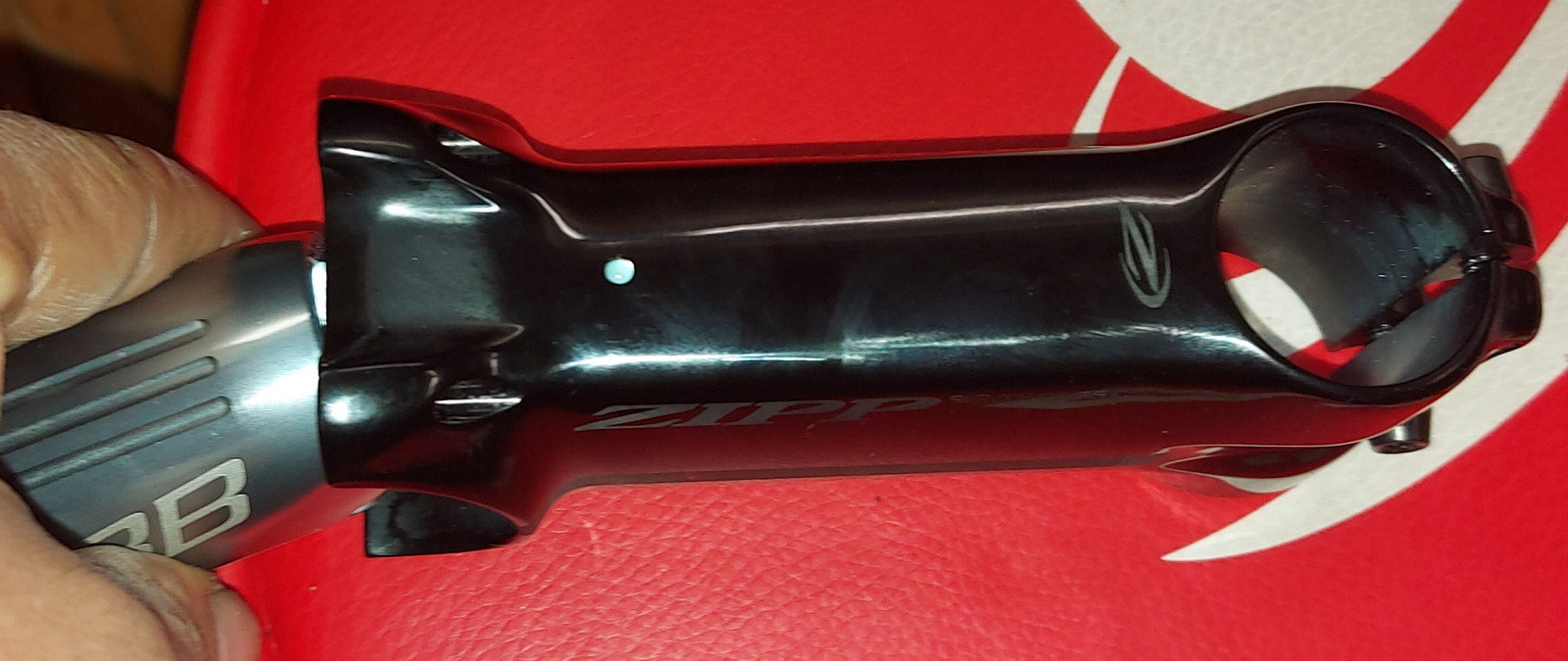
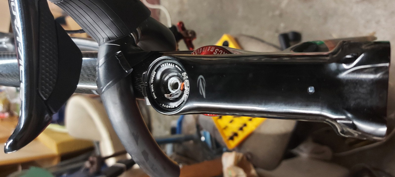
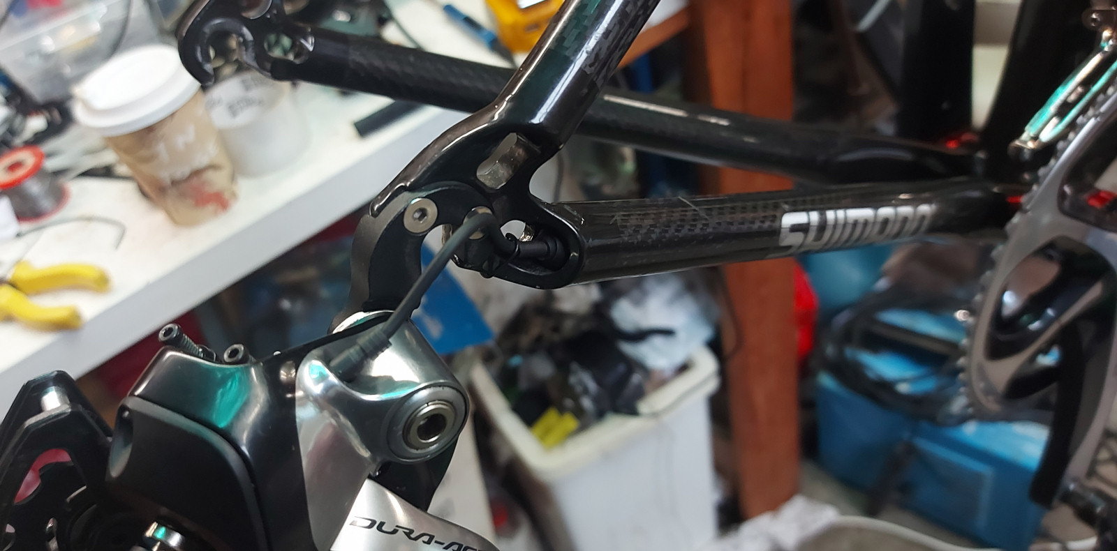
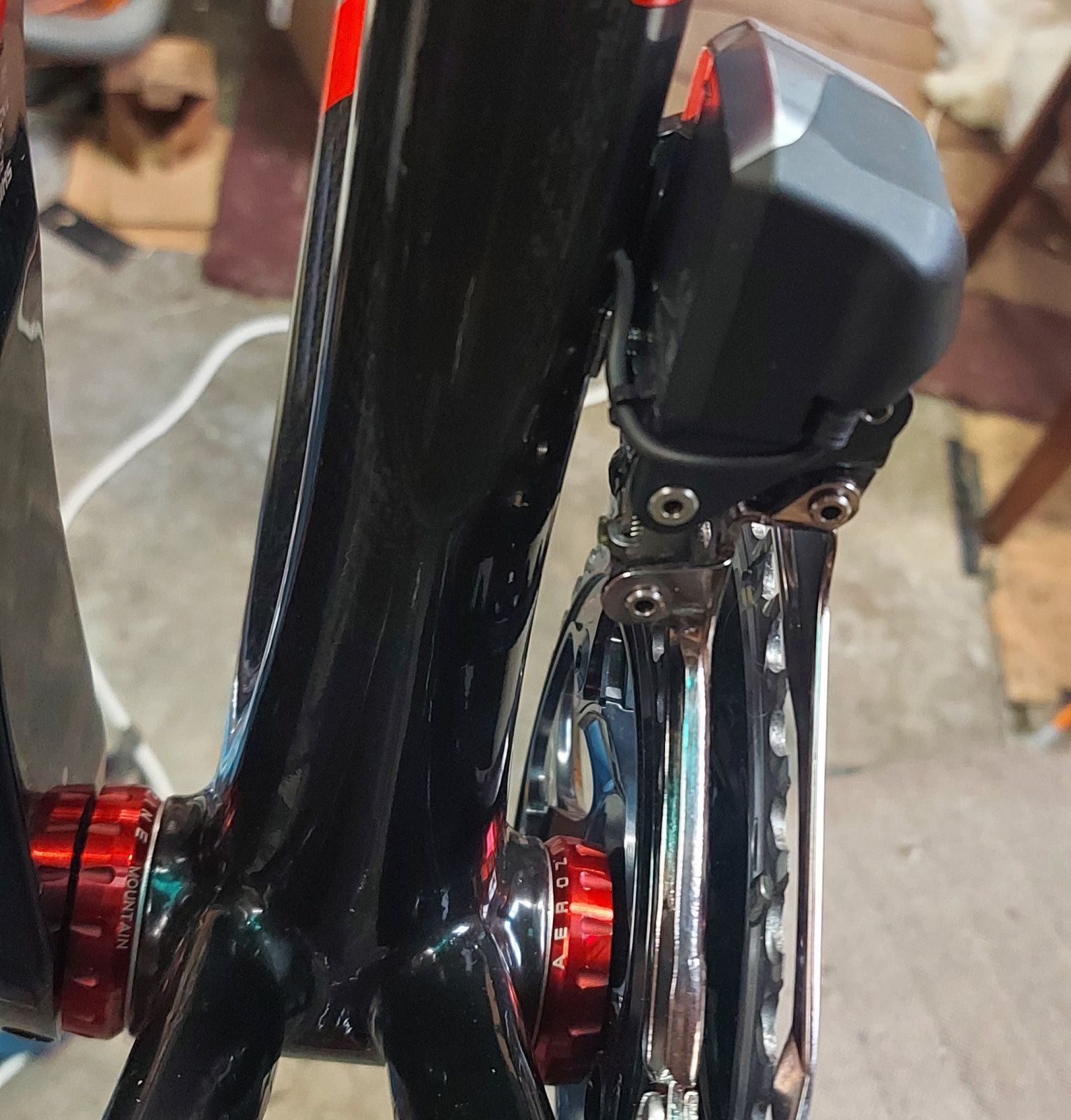
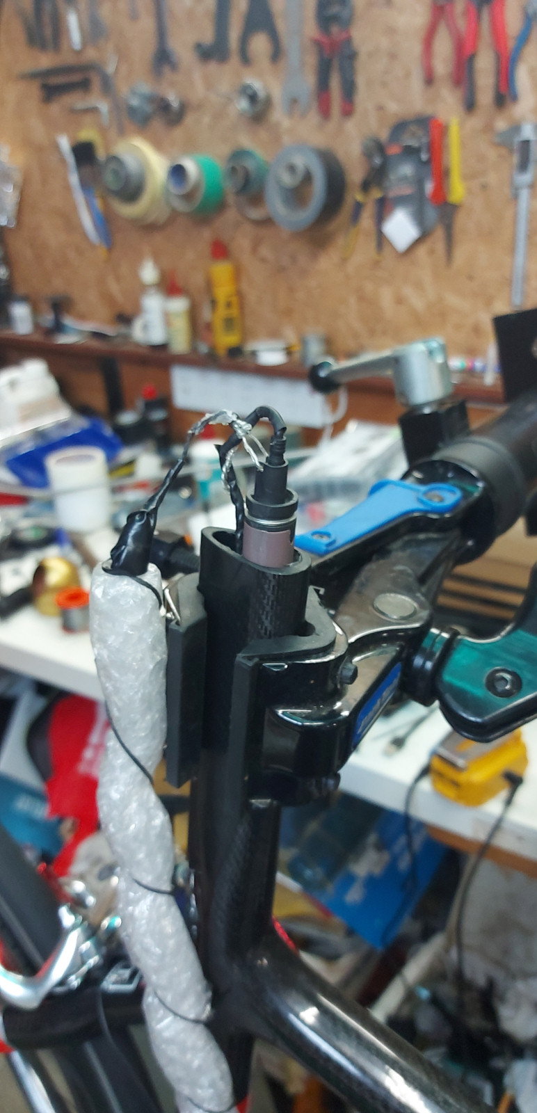
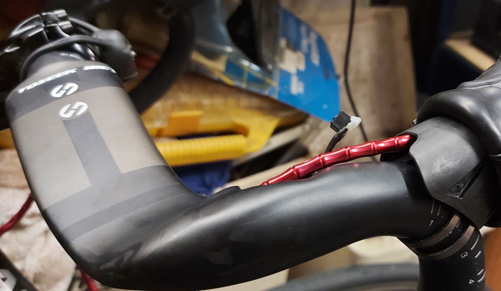
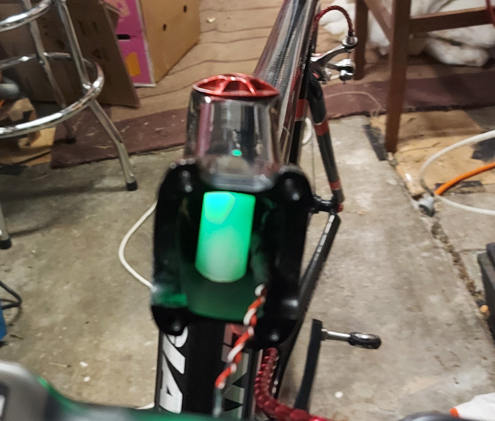
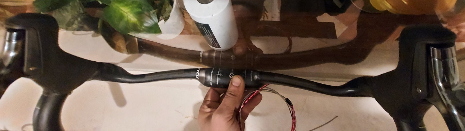
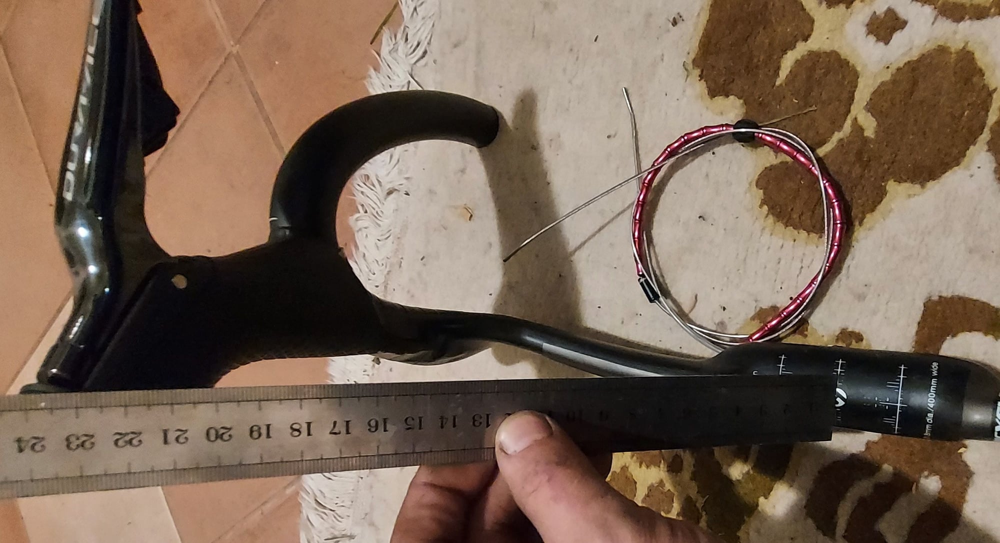
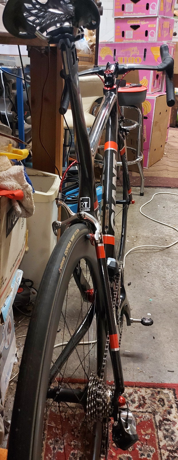
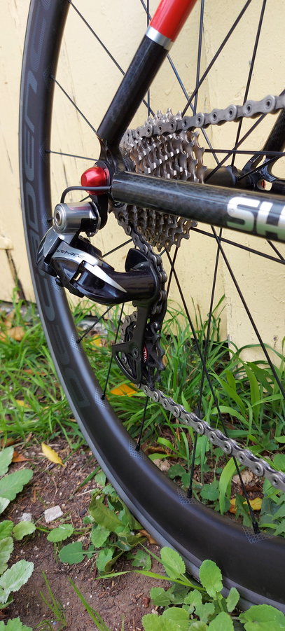
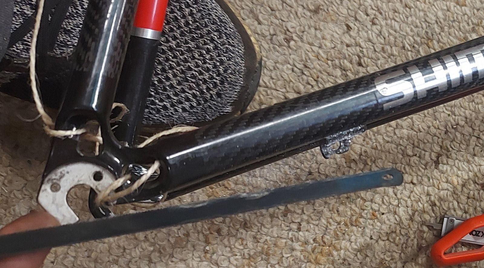
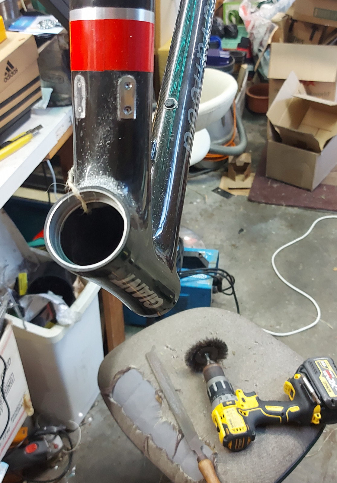
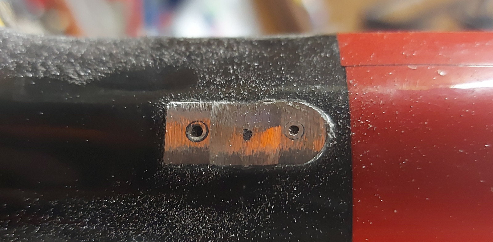
The SM-EW90-A is now just a tiny PCB inside the stem, hotglued into a section of sealant gun nozzle, which locates it and also serves as a light pipe to a small hole in the top of the stem, plugged with hotglue - it looks just like a 2.5mm LED! Sweet. There's a headphone jack from a phone for the ground and signal, plus the junction A button (just contacts ground, so only three wires needed), which is moved up just behind the right shifter. It's a pretty trick retromod if I do say so myself... had to make a couple of 1.8mm holes in the carbon steerer, a 2mm hole in the bars (in the lower part of the section looking into the stem, fingers crossed those fibres weren't too important), a 3mm hole behind the FD, and a couple of 3mm holes in the BB shell to the seat tube and chainstay (they could've been smaller, but those drillbits weren't long enough). I reckon I've probably avoided any serious structural compromise.


You might wanna play it at 1.25 or 1.5x... my video production is a bit crap.


Going the hack on cable guides:

Image

Image

Here's a trick I came up with to stop the file skating off into the paint:

Image

With the dip in the middle, it's a lot easier to hold it square.
Last edited by Kimmoth on Fri Jun 25, 2021 12:06 pm, edited 1 time in total.

User avatar
Kimmoth
Posts: 87
Joined: Wed May 30, 2018 11:33 am
Location: Melbourne, Oz
Contact:

by Kimmoth

I started mousing the frame with a front brake cable offcut, the welded end ground smooth and the cut end taped to some twine (had no fishing line). Used a bit of liner tube here and there to help.

Image

The twine was pretty crap. Needed something a bit stiffer, so busted out some ABS 3D printer stock.

Image

I did use the twine, plaited with the loom wires, to add some fuzzines to the wire, and used extra length and coiled it to try and mitigate any noise... Joining stuff to the printer stock without creating a snag point was a bit of a trick.

Image

by Weenie


Visit starbike.com Online Retailer for HighEnd cycling components
Great Prices ✓    Broad Selection ✓    Worldwide Delivery ✓

www.starbike.com


User avatar
Kimmoth
Posts: 87
Joined: Wed May 30, 2018 11:33 am
Location: Melbourne, Oz
Contact:

by Kimmoth

Bought some diamond bits for my Dremel to do the holes in seat tube, bars and steerer. Had to use a bit shaped like a sharply tapered cone with a little ball on the end to soften the inside corner of the hole enough to be able to drag the wire through - no poking it through when the steerer's inside the head tube.

Image

These holes are about 1.8mm.

Image

Repurposed charger plug, with most of the bulk hacked off it

Image

Ditto for the jack. This had an O-ring on it... when I took it off the jack, I expected it to be a normal O-ring, but nope. Square. Shimano doesn't take any shortcuts; the EW50 wires I hacked up for the plugs are that expensive because they're the toughest wires anywhere near that size I've ever stripped.

Image

User avatar
Kimmoth
Posts: 87
Joined: Wed May 30, 2018 11:33 am
Location: Melbourne, Oz
Contact:

by Kimmoth

Here we can see that pair of connectors hotglued where the downtube meets the head tube. I had to leave extra length on the wire to be able to do this, and the knot leaves me the right amount of slack between the glued plug and the steerer after I've inserted the fork and dragged the excess wire out.

Image

Fiddly business. Phew

Image

Here's where I discovered that a couple of little holes in the top part of the expander plug (not shown here) wasn't enoiugh; I also needed to file a groove through the lower knurled section and O-ring groove, to allow me to push the expander plug down into position. The upper hole in the steerer was originally going to be bang in the middle of the stem's height, but something told me it'd take away less strength if I moved it up to just below the upper knurled section.

Image

User avatar
Kimmoth
Posts: 87
Joined: Wed May 30, 2018 11:33 am
Location: Melbourne, Oz
Contact:

by Kimmoth

Check out the SM-EW90-A PCB! Some really tiny surface-mount stuff on it, like in a phone.

Image

First go at wiring it up

Image

A pair of wires runs back into the steerer and up through the compression plug to join the wires coming from the frame up through the steerer. This join has to be unsoldered to get the stem off, since there's no room for a plug under the top cap. Initially, another two pairs of wires was running forward into the bars, the extra pair for the remote A-junction button. Finding a suitable connector for four wires was a PITA. Surface-mount micro USB jack gave barely more than a pinprick-sized area to solder onto

Image

But with the aid of my phone on a tripod running a magnifier, I did it by employing ye olde Ultra DMA HDD ribbon wire. Of course, it promptly shat the bed during assembly with the hotglue and heatshrink.

Image

User avatar
Kimmoth
Posts: 87
Joined: Wed May 30, 2018 11:33 am
Location: Melbourne, Oz
Contact:

by Kimmoth

Plan B, ditch the wire I suspected was surplus to requirements - there's like 0.3ohms between one of the contacts on the A junction button and the black wire in the the Di2 loom, and whaddayaknow, that's the go. So here's a far less hair-tearing headphone socket from the same pillaged phone.

Image

Also shown is the section of glue gun nozzle I carved up to serve as a mount for the PCB and light pipe for the LEDs. PCB hotglued into it

Image

And here we've got my $40 wing and a prayer Aeronova ripoff with a 2mm hole in it. After considering it, I decided to put the hole as low as I could, which seemed to make a lot of sense.

Image

User avatar
Kimmoth
Posts: 87
Joined: Wed May 30, 2018 11:33 am
Location: Melbourne, Oz
Contact:

by Kimmoth

I initially got my order of operations a bit screwed up, and found myself having to drill the hole in the stem with it on the bike... not good - it came out a tad off-centre. This was during plan A with the four wires, so the thing had to come off again. Luckily this hole was only 1.5mm, so with a bit of careful dremelling with a skinny diamond bit, I widened it out so I could make a nice 2.5mm hole on centre.

Image

Looks pretty freakin' sweet with a blob of hotglue in it, nearly as good as I hoped for. Very slightly countersunk by hand to deburr it, a bit of black marker in before the glue, and it looks mint. Maybe a dab of epoxy on top to make it flush...

Image

Little bit of wire to hold the RD cable just so

Image

FD cable neat AF

Image

User avatar
Kimmoth
Posts: 87
Joined: Wed May 30, 2018 11:33 am
Location: Melbourne, Oz
Contact:

by Kimmoth

Here's the battery, shaved about a mm down each side to fit into the seat mast (I filed along the join, down to the groove, didn't go through the casing), with a couple of tiny holes drilled in the square bit on top, where I've got a bit of wire rigged up to orient the thing for removal. Kevlar string attached to that, wound around some rolled-up bubble wrap.

Image

This lot gets stuffed down the seat tube as far as possible with a large poking implement of some sort, and the end of the kevlar is secured in the top of the seat mast with a small blob of blutack.

Image

Ta-daa! Pretty much finished. Just gotta take it for a spin and dial in my position (I've swapped a 17/110 for this 8/100 stem), fit a little button onto those bare wires, and get some fresh bar tape on there.

Image

User avatar
Kimmoth
Posts: 87
Joined: Wed May 30, 2018 11:33 am
Location: Melbourne, Oz
Contact:

by Kimmoth

Got around to dialling in my new position (getting old, changed my stem from 17/110 to 8/100), got some fresh bar tape, pillaged the middle-click button from a mouse

Image

Here's a shot of the hidden A junction doing its thing

Image

Once I figure out where I want the levers, I put a lot of effort into making them symmetrical

Image

Glass is flat

Image

Lots of trial and error, due to the fact the height changes with rotation

Image

User avatar
Kimmoth
Posts: 87
Joined: Wed May 30, 2018 11:33 am
Location: Melbourne, Oz
Contact:

by Kimmoth

Oh yeah

Image

Image

Image

Image

Image

Image

theStig
Posts: 421
Joined: Mon Aug 06, 2007 1:22 am

by theStig

Good work! Reminds me I have to hack up some FDD cables to make a 3DFX SLI adapter..

User avatar
Kimmoth
Posts: 87
Joined: Wed May 30, 2018 11:33 am
Location: Melbourne, Oz
Contact:

by Kimmoth

Gee, there's a blast from the past

User avatar
jagheterjan
Posts: 66
Joined: Fri Jul 17, 2020 10:41 am
Location: Fat bloke on a TCR

by jagheterjan

I'm lovin it

User avatar
Kimmoth
Posts: 87
Joined: Wed May 30, 2018 11:33 am
Location: Melbourne, Oz
Contact:

by Kimmoth

Oh yeah, did this too, jammed 12/14t in the 9070

Image

Image

by Weenie


Visit starbike.com Online Retailer for HighEnd cycling components
Great Prices ✓    Broad Selection ✓    Worldwide Delivery ✓

www.starbike.com


Singular
Posts: 537
Joined: Mon Jul 27, 2020 8:59 am

by Singular

Proper modding there!

Post Reply