


Hi Revver
By coincidence I have given this some thought and sketched a couple of ideas some time ago. I'd make it removable maybe held on with clips or ¼ turn fasteners. To be honest I'm not convinced how effective it would be on a road bike as opposed to a straight line TT ride. Once the front wheel is turned it would instantly upset any aero gain. Cross winds maybe an issue, imagine turning a bend straight into a side wind! I'd be interested in seeing some wind tunnel tests on a setup.
From a production point of view I'd make the shape/plug from expanded foam covered in filler, sand it into shape and then make a female mould from fibreglass. The carbon male part would then be produced with a perfect exterior finish, far quicker and gives more control over material thickness etc. As it's non structural I'd use 2ply with 4-5 layers along the leading edge and possibly 3 along the flanks. Again using the above mould technique you could add additional layers of required once it's out of the mould. As for weight, rather difficult to say without measuring the area to be modelled. A rough guess a minimum of 50g upto 100+g
Are you planning on such a mod?
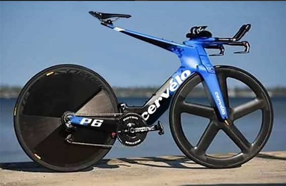
Trek Y Foil 77. An iconic classic brought bang upto date.
Moderators: MrCurrieinahurry, maxim809, Moderator Team


Visit starbike.com Online Retailer for HighEnd cycling components
Great Prices ✓ Broad Selection ✓ Worldwide Delivery ✓
www.starbike.com
I'm thinking about it. Another plan would be to carve rigid foam into the desired shape. An aero pocket for the chainring could be included. Then cover all sides except the bottom with CF, Next hollow out the foam removing as much as possible, CF the bottom. For mechanical shifters, dremel a slot in each side and leave a slot open in the bottom. Use an adhesive, ShoeGoo or Goop, to glue the finished form to the "down tube".


-
theblackgold
- Posts: 8
- Joined: Wed Mar 02, 2016 9:42 pm
We don't Care. Do it! Fabrication is always nice to see
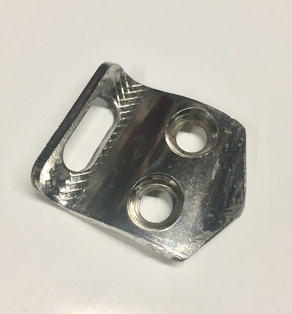
Another area in need of some weight removal is this little front mech hanger/braze on, quite a hefty piece of chromed steel!
As far as I can tell this is unique to the Trek Y Foil although Im sure someone will prove me wrong and say that its a standard shape and one is available off the shelf.
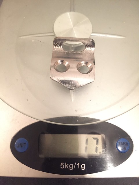
Im going to reproduce it in carbon, I have no idea what the finished weight will be at this stage but at a guess hopefully half of the existing 17g.
So here we go....
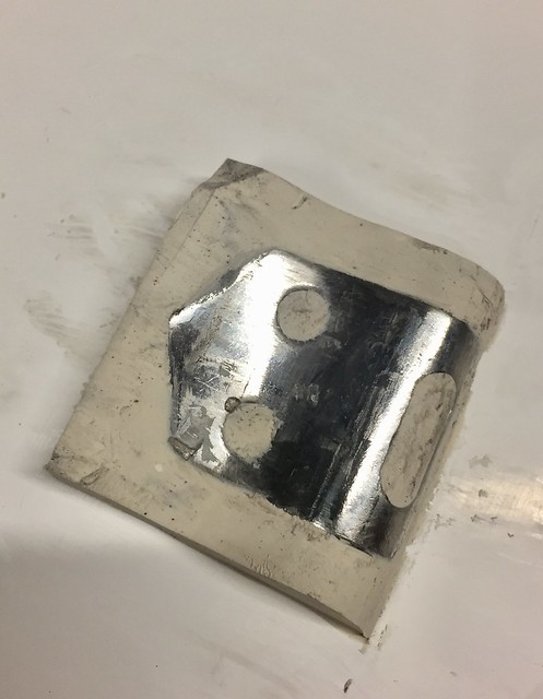
First job is to press the steel into modelling clay and scrape it flush against the front face.
I forgot to photograph one VERY important step thats the one of applying blue release agent at this stage.
Once its dried paint on a white gel coat, allow to dry again very important to allow it to dry.
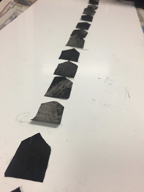
Once dry four layers of glassfiber matting and resin are stippled on. Not the nicest looking thing at this stage.
Once its all set I cut the edges of to square it up and remove the scrappy areas.
This view is looking from underneath at the modelling clay, at this stage its model clay and fibreglass with the steel mech hanger sandwiched inside. It will pop out easily once the blue release agent is soaked with water.
Once the clay is removed heres the first half of the mould with steel plug/hanger in place.
I will fill the holes flush with model clay and paint on more blue release agent before applying an initial white gel coat.
Gel coat applied and drying
Heres the second face of the mould added. So now the sandwich from one side to the other consists of Fiberglass matting in resin>white gel coat>blue release agent>steel plug>blue release agent>white initial gel coat>fibreglass matting in resin.
Once its cured pop open the mould by allowing the blue release agent to dissolve in water, and out it pops.
Here are the various parts all apart, the little pieces of clay are thrown away and the steel hanger cleaned off.
All of the remaining release agent is washed out leaving a smooth white female inner surface of the mould.
some cleaning up and sanding is required around the clay areas of the holes etc.
Finally more release agent is applied and allowed to dry, notice the little moulded in lugs that will unsure both halves line up when pressed together.
Its now ready to make a carbon front hanger, stay tuned
As far as I can tell this is unique to the Trek Y Foil although Im sure someone will prove me wrong and say that its a standard shape and one is available off the shelf.
Im going to reproduce it in carbon, I have no idea what the finished weight will be at this stage but at a guess hopefully half of the existing 17g.
So here we go....
First job is to press the steel into modelling clay and scrape it flush against the front face.
I forgot to photograph one VERY important step thats the one of applying blue release agent at this stage.
Once its dried paint on a white gel coat, allow to dry again very important to allow it to dry.
Once dry four layers of glassfiber matting and resin are stippled on. Not the nicest looking thing at this stage.
Once its all set I cut the edges of to square it up and remove the scrappy areas.
This view is looking from underneath at the modelling clay, at this stage its model clay and fibreglass with the steel mech hanger sandwiched inside. It will pop out easily once the blue release agent is soaked with water.
Once the clay is removed heres the first half of the mould with steel plug/hanger in place.
I will fill the holes flush with model clay and paint on more blue release agent before applying an initial white gel coat.
Gel coat applied and drying
Heres the second face of the mould added. So now the sandwich from one side to the other consists of Fiberglass matting in resin>white gel coat>blue release agent>steel plug>blue release agent>white initial gel coat>fibreglass matting in resin.
Once its cured pop open the mould by allowing the blue release agent to dissolve in water, and out it pops.
Here are the various parts all apart, the little pieces of clay are thrown away and the steel hanger cleaned off.
All of the remaining release agent is washed out leaving a smooth white female inner surface of the mould.
some cleaning up and sanding is required around the clay areas of the holes etc.
Finally more release agent is applied and allowed to dry, notice the little moulded in lugs that will unsure both halves line up when pressed together.
Its now ready to make a carbon front hanger, stay tuned
-
Frankie - B

- Admin - In the industry
- Posts: 6573
- Joined: Mon Jun 02, 2003 8:17 am
- Location: Drenthe, Holland
Bernhard of BTP used to have these hangers in his web shop. they were a cool piece of kit. I'm looking forward to see what you come up with.
If you want to see 'meh' content of me and my bike you can follow my life in pictures here!'Tape was made to wrap your GF's gifts, NOT hold a freakin tire on.'
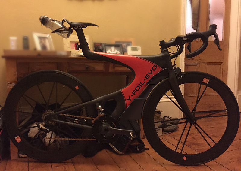
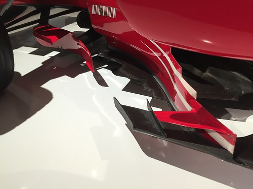
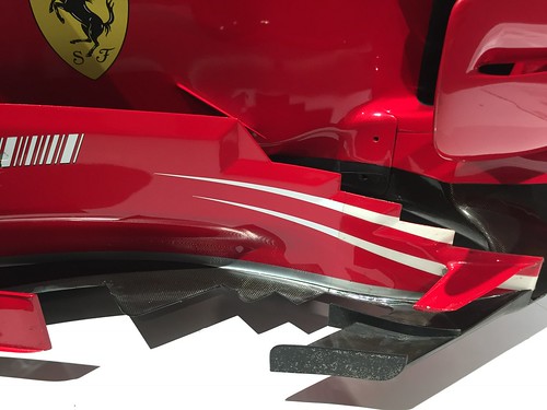
I’ve been giving this some thought over the past few days, rather than have a solid formed shape on the leading edge I like the idea of ‘aiding’ airflow by use of a spoiler or splitter system. Usually more in keeping to something on a Formula F1 car. In addition to their large front and rear downforce spoilers they also use numerous splitters to help flow air around the car, guiding air into areas of use for engine/brake cooling etc.
On the bike a single thin blade could run down the downtube filling that space between wheel and frame, two small splitters on either side could help guide air around the front headtube/forks crown and downtube. This arrangement would also be useful in cross winds, rather than being a large solid shape air could pass around the splitter edges and flow past the frame (rather like a slatted timber fence panel)
Ive knocked up a quick Photoshop image showing the idea. Sorry for the awful photo I just snapped it quick in our hallway, how many pairs of bloody shoes does one house need!!
Anyway is this just a plain stupid crazy idea I wonder?? or is it something worth developing.
Im bracing myself to be laughed off the forum with this one!!
Last edited by Clannagh on Wed Nov 16, 2016 6:04 pm, edited 1 time in total.
Visit starbike.com Online Retailer for HighEnd cycling components
Great Prices ✓ Broad Selection ✓ Worldwide Delivery ✓
www.starbike.com


