Back by popular demand, the general all-things Road forum!
Moderator: robbosmans
-
Artisan
- Posts: 2
- Joined: Sun Aug 14, 2011 10:52 am
- Location: Melbourne
-
Contact:
by Artisan on Mon Oct 08, 2012 6:51 am
I'm in the process of dissecting an EPS power unit in an attempt to reduce it and find a more 'stealth' position on or in a frame.
Has anyone on WW tried to use a seperate power source and/or place the 'brain' in the frame? It's not a small unit and could prove problematic trying to waterproof properly.
If I actually manage to pull this off, I will post more. Otherwise

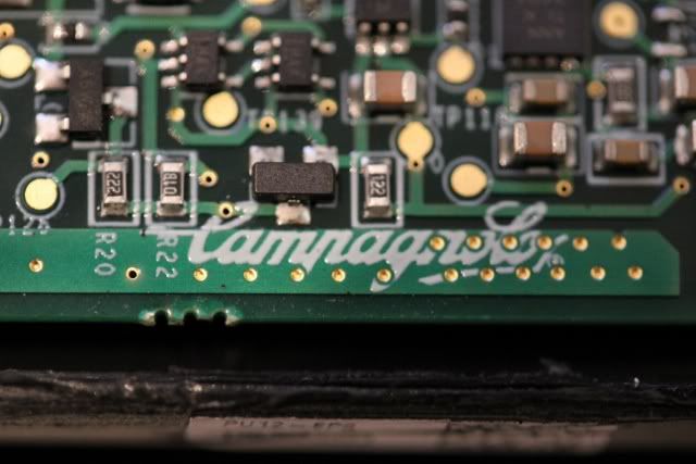
Here is a sneak peek.
-
Omiar
- Posts: 386
- Joined: Wed Dec 14, 2011 8:20 pm
by Omiar on Mon Oct 08, 2012 7:41 am
Is the PCB small enough, so that after removing the battery and making a custom case for the PCB, it still fits inside a frame?
Cannondale SystemSix R8170
Trek Checkpoint SL5 MY2022
-
maxxevv
- Posts: 2012
- Joined: Wed Feb 09, 2005 4:51 am
by maxxevv on Mon Oct 08, 2012 3:11 pm
If you want a relative size, the SMD marked at R20 (222 on it) is approximately 1.5~2 mm in width (measured left to right). When you scale up the board as we see here, you get the relative scale of things.
From what I've seen for embedded devices, this is quite big comparatively, especially considering we are not seeing the whole board yet.
-
Artisan
- Posts: 2
- Joined: Sun Aug 14, 2011 10:52 am
- Location: Melbourne
-
Contact:
by Artisan on Wed Oct 10, 2012 8:31 am
The PCB or whatever it's called is almost the height (width) of the EPS power unit (40mm). The battery is rather small and I'm sure open to options in the future.
After speaking to a few people, the hard part will be to leave the PCB intact and re-house it safely and not mess with the electrical conductivity/signals (I'm obviously no electrical expert). I'm hoping to re-connect the battery seperately and allow the two seperate units to be placed inside a frame.
One thing though, I don't think anyone will be putting one inside a stem...
It (was) a very well made, water tight unit. No question about that!
-
mrfish
- Posts: 1749
- Joined: Wed Mar 28, 2007 12:49 pm
- Location: Near Horgen, Switzerland
by mrfish on Wed Oct 10, 2012 8:40 am
I would take a look at how electric helicopter / boat / car crowd package their electronics. On helis they use heavy duty heatshrink to protect speed controller electronics and that's it. Not familiar with the others, but I'm sure a search at rcgroups.com and a couple of questions will help.
-
sugarkane
- in the industry
- Posts: 1797
- Joined: Wed Jan 19, 2011 11:14 am
- Location: SYD
-
Contact:
by sugarkane on Wed Oct 10, 2012 9:16 am
you could also set the controller pcb in epoxy that will environmentalize the unit pretty well.. you wana be sure of what your up to though as once its done, its done
-
maxxevv
- Posts: 2012
- Joined: Wed Feb 09, 2005 4:51 am
by maxxevv on Wed Oct 10, 2012 9:18 am
Maybe you can post some picts of the complete board next to a ruler ? (40mm width seems bigger than what I was expecting. What about length ?)
It would be useful for people to come up with suggestions of how to package it though.
-
Omiar
- Posts: 386
- Joined: Wed Dec 14, 2011 8:20 pm
by Omiar on Wed Oct 10, 2012 4:31 pm
I wouldn't be too worried about the re-housing.
I would suggest to have the case 3D printed. I would use a profile joint between the two sides and use some sealant when putting it togheter. For connectors, source some MIL grade connectors from local Radioshack store.
Cannondale SystemSix R8170
Trek Checkpoint SL5 MY2022


